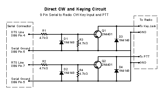
Direct Serial Port CW & PTT Keying Circuit
Posted By:
Rob Mavis AE6GE
Posted On: 2025-09-25T20:37:10Z
When I was getting ready for this year's California QSO Party, I realized I wanted my logging computer to do the CW keying for the radio instead of juggling paddles or hand-keying while logging. Programs like N1MM can handle CW generation beautifully — but only if the PC can key the rig. That sent me down the rabbit hole of simple keying interfaces. After some experiments, I landed on this straightforward two-transistor design that was cheap and quick to build.

Why this design?
- Simplicity: Just two NPN transistors and a few resistors/diodes.
- Compatibility: Mimics a straight key or PTT switch closure to ground.
- Safety: Clamp diodes protect the transistors from RS-232 swings.
How it works
- DTR (pin 4) → drives the CW transistor (Q1) through R1 (4.7 kΩ).
- RTS (pin 7) → drives the PTT transistor (Q2) through R2 (4.7 kΩ).
- Each base has:
- A 1N4148 diode to ground (protects against negative RS-232 swing).
- A 4.7 kΩ pull-down to ground (ensures “off” when idle).
- Each collector goes to the radio’s KEY/PTT input and is shunted by a 1N4148 diode for RF/transient protection.
- Each emitter ties to DB-9 ground (pin 5) and to the radio ground.
When N1MM asserts DTR or RTS, base current flows, saturating Q1/Q2 and shorting the radio line to ground — exactly what the rig expects.
Build Parts List
- 2 × 2N4401 (Q1/Q2)
- 4 × 1N4148 (D1–D4)
- 4 × 4.7 kΩ resistors (R1–R4)
- DB-9 connector (male/female to match your adapter)
- Jacks for KEY and PTT lines (often 3.5 mm mono plugs)
- Small perfboard + box enclosure (optional)
N1MM setup
- Config → Configure Ports → add your COM port.
- Assign CW keying to DTR (pin 4).
- Assign PTT to RTS (pin 7).
- Invert DTR/RTS if needed (depends on idle logic of your adapter)
Direct CW and Keying Circuit.pdf